Liquid Oxygen Filling Station: Operational Guidelines and Safety Framework
As vital nodes in cryogenic gas distribution networks, liquid oxygen (LOX) filling stations enable the transfer of -183°C oxygen between air separation plants and transport vehicles. Their design follows NFPA 55 and EN 1089-3 standards, addressing both cryogenic risks and oxygen enrichment hazards through engineered controls.
Key Subsystems
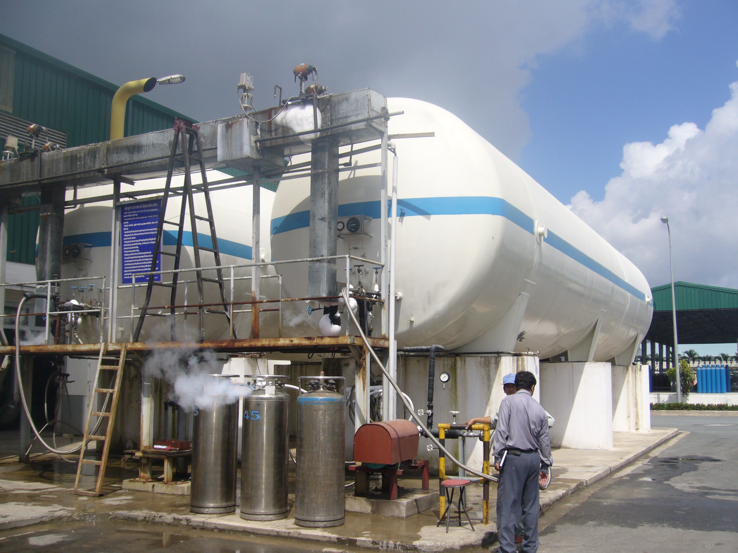
2.1 Cryogenic Containment
Vacuum-insulated storage tanks (304SS inner vessel/carbon steel outer vessel)
<0.5% daily evaporation rate via multi-layer insulation
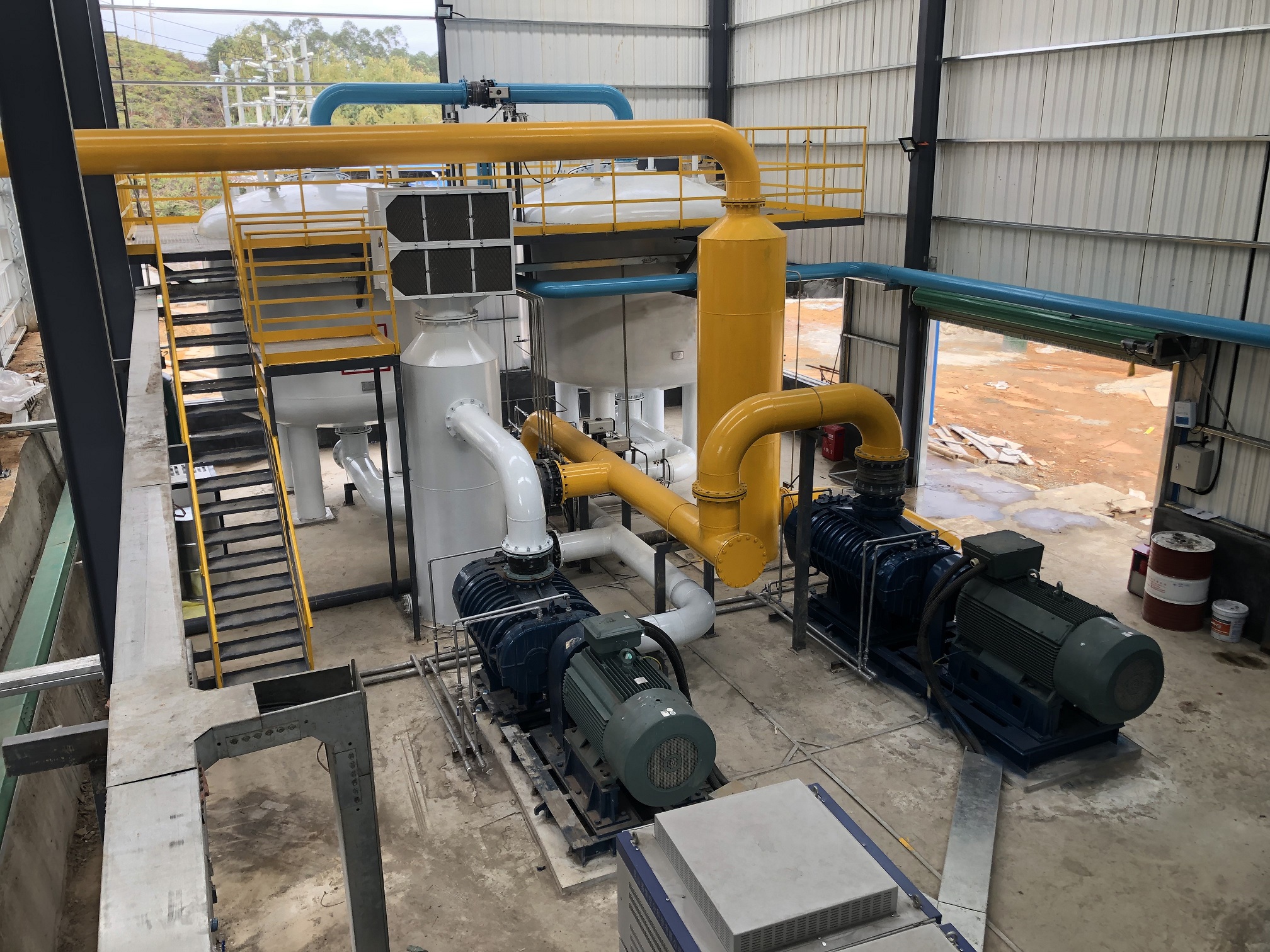
2.2 Phase Conversion Modules
Primary finned-tube ambient vaporizers (500-2000 Nm³/h capacity)
Secondary water-bath vaporizers for peak demand scenarios
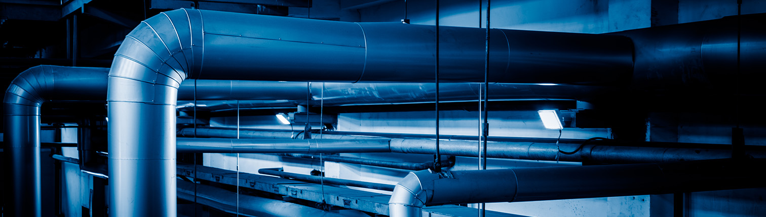
2.3 Transfer Infrastructure
ASME B31.3-compliant SS316L piping with PTFE seals
Dual-stage relief valves (20 MPa operating/24 MPa relief)
Safety Protocols
3.1 Hazard Mitigation
30m restricted access perimeter
Continuous O₂ monitoring (23.5% vol alarm trigger)
<10Ω equipotential bonding
3.2 Standard Operating Procedures
Triple nitrogen purge cycles (<50 ppm residual)
Gradual cool down sequencing (-196°C to -183°C in 3 stages)
Load cell-controlled filling (±1% mass tolerance)
3.3 Contingency Planning
Type D dry powder suppression systems
Secondary containment dykes (1.1× tank volume)
Cryogenic first-response kits
Sector-Specific Implementations
4.1 Medical Gas Networks
Hospital bulk supply systems (meeting ISO 7396-1:2016)
4.2 Launch Vehicle Operations
Cleanroom-compliant propellant filling (per ESA ECSS-Q-ST-70-71C)
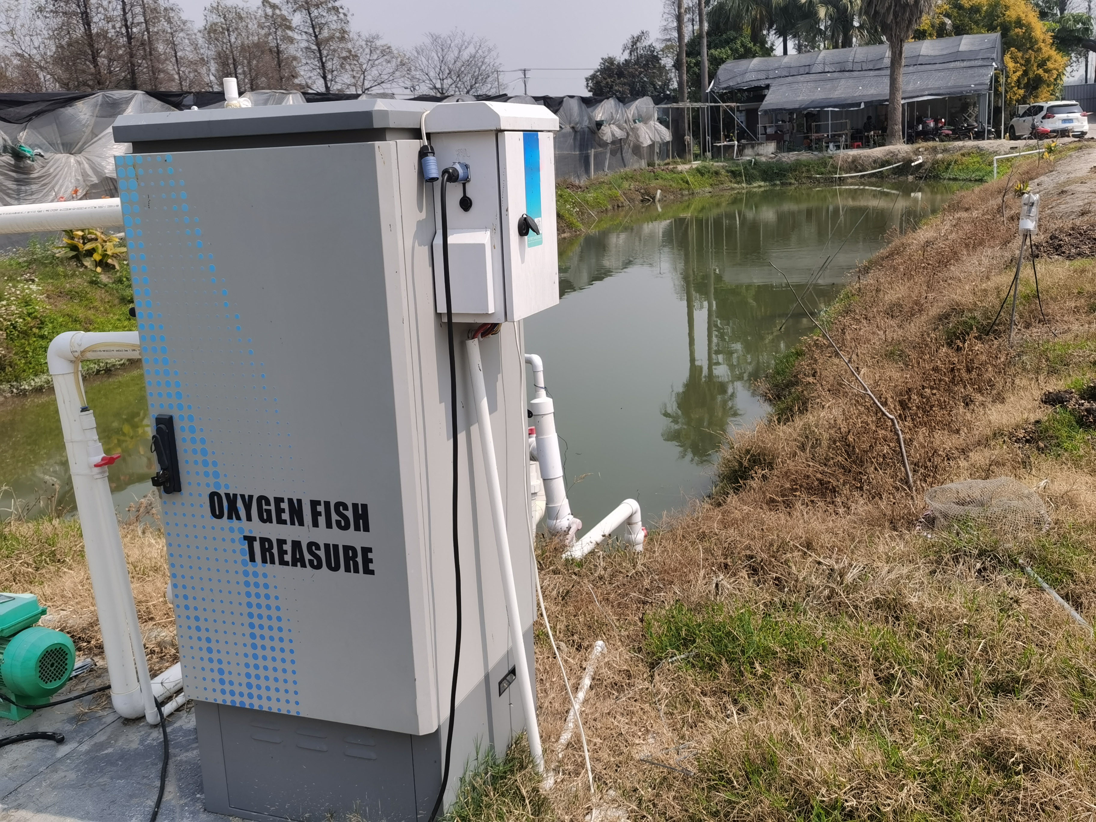
4.3 Advanced Oxidation Processes
Sludge reduction systems achieving 35% volume decrease
Emerging Technologies
Real-time telemetry via LoRaWAN sensors
FFT-based vibration diagnostics for predictive maintenance
Hydrogen-cycle compression (30% energy reduction)
Per 2024 CGA operational data, contemporary installations maintain 99.99% uptime through these multi-layered safeguards.


 H2 plant Hypower Project wind power to H2 2000NM3 per hour (1).jpg)
.jpg)